Refers to 02.06.01 and 02.07.01
From the Measurer’s Report, IMCCA General Assembly IMCCA:
“(…) there were several rudder failures again. This leads some clubs to refuse the Micros for regatta at sea. Sadly, it is very difficult to imagine new rules affecting rudder construction.”
Rudders of Micro’s use to fail in bad wind and wave conditions.
This is not unavoidable. But writing rules to reduce failures is a very difficult exercise, so we think you are free to do what you want, we will only help you understanding how you could correct the weaknesses.
Sources of failures may be:
- delamination of the rudder blade;
- rupture of the rudder blade under the lower fitting;
- failure of the rudder fittings, usually the lower one.
The rudder may be submitted to tremendous constraints, and the usual shape of a Micro transom doesn’t help resisting these constraints.
First point: constraints analysis
The forces on the rudder are shown as shown on picture on the right. In normal conditions, there shouldn’t be major problems, but when the boat is heeled, the immersed area is reduced while the distance between the lift and the fittings is increased. In addition, at 20 degrees of heel you need 10% more lift on the rudder to achieve the same horizontal component.
At moderate speed, the force should be limited by loss of lift (stall) due to a high angle of attack. But at high speeds, the lift is proportional to the square of speed, and a high lift is generated without reaching high angles of attack. At 20 degrees of heel, the constraint on the lower fitting may be increased by as much as 25%, we don’t speak about 30 degrees…
Modern high aspect ratio rudders are more prone to fail, because the force can apply at a larger distance, and these rudders are very thin.
The most important constraint is applied to the lower fitting, and the weakest part in this area will fail.
The force applied on the rudder blade is also generating a high shearing constraint at the level of the junction between the two sides of the blade.
Second point: failure analysis
Failures of the first type are due to shearing constraints, and rudder fail only because the liaison between the two shells of the outer skin is weak. Usually, the shells are glued to each other with a mix of gelcoat and micro-balloons. This could be easily cured, for instance by a careful stratification of roving / polyester on the leading and trailing edges, it is not easy, it required a lot of fairing work.
A liaison glue on a wide liaison plane is another solution, 6 to 8 millimeters of good contact is required. In addition, a good central plate fixed on one shell, with the gluing occuring on the other shell at the widest point, will reduce breaks by shearing.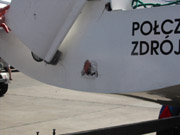
Failure by breaking the blade (when not originally caused by delaminating) can be avoided by very strong construction. A “H” profile inside is a requirement. But the constraints can be dramatically reduced by positioning the lowest fitting as low as possible.
Failure of the fittings, when not caused by improper mounting (see picture of POL-44 Soncas, there were NO large washers inside), can be reduced by increasing the distance between the fittings.
Formulas
To have an idea of the constraints generated…
At 5 knots, a rudder blade of 1,00 m by 0,25 m can generate up to 100 kg (981 N) of lift: 0,5*SG*CL*A*v2 with SG (specifig gravity)=1026 for sea water, CL (lift coefficient) up to 1,25 and v=2,5 m/sec.
The distance d1 between the centre of lift of the blade can be some 0,55 m, so 55 kg.m (540 N.m) is applied at the lowest fitting. A rudderblade of 20 mm maximum thickness, 14 mm average thickness, should be made of a laminate resisting more than 8000 kg (78500 N)…
If the distance d2 between the fittings is 0,30 m, the force on the upper fitting is 55/0,30 or 180 kg (1770 N), and the total force on the lower fitting is 100+180 kg = 280 kg (2750 N)…
When the distance between fittings is reduced to 0,20 m, the force on the upper fitting is 270 kg (2650 N), and 370 kg (3630 N) on the lower one. All these values are increased by…
25% for 20 degrees of heel with same horizontal force applied;
44% for the first knot in addition;
300% for twice the speed – and Micro’s can do it…
And the strength of a rudderblade is increased by no less than 73% for 20% thickness increase. Perhaps you should use a thin rudder in light weather and a thicker one in a breeze.
Conclusions
Think of…
- a sound construction is required at all stages (rudder construction, strong fittings, strong counterplates on the transom);
- maximise the distance between the fittings;
- very thin rudders are weak by nature;
- when a Micro is hard to sail at high speed, reduce the lift of the sails and don’t try to steer her only with the helm.